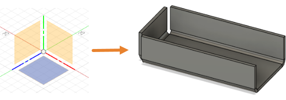
A sheet metal part starts out as a flat piece of metal with a consistent thickness. A flange feature consists of a face and bend connected to an existing face along an edge. This tutorial shows you how to create a sheet metal flange and convert the part into a drawing for manufacuture.
In this tutorial, you
- Create a simple sheet metal part from scratch, using Sketch commands to create a profile for a base face, and the Flange command to create a flange along the edges
- Create a new rule and apply it to the sheet metal part
- Create a flat pattern and subsequently a drawing for manufacturing, using the flat pattern.
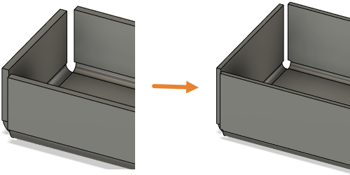
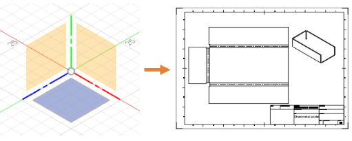 Sketch environment ready to start (left). Drawing for manufacturing (right).
Part 1: Create a sheet metal flange from a sketch profile
In this activity, you create a simple sheet metal flange. To accomplish this you
- Confirm your document settings are set to mm
- Create a closed sketch profile using the 2-Point Rectangle command
- Create a base flange from the sketch profile
- Add features to the base flange to create the sheet metal flange.
Steps
- Confirm that your document settings are set to mm.
- In the Browser expand
 Document Settings.
 - Confirm the
 Units are set to mm.
 - If you need to change the units, hover over Units and click
 Change Active Units
 - In the Change Active Units dialog, change the Unit Type to Millimeter.
- Click OK to accept the command and close the dialog.
- In the Browser expand
- Using the commands in the Sheet Metal tab, create a closed rectangular sketch profile, measuring 100 mm x 50 mm.
- Click
 (Design workspace > Sheet Metal tab > Create panel > Create Sketch) to initiate a sketch.
 - Select a sketch plane, to open the Sketch Palette.
- Click
 (Design workspace > Sheet Metal tab > Create panel > 2-Point Rectangle) to activate the 2-Point Rectangle command.
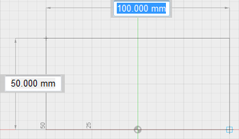
 - Click on the canvas to place the first point of the rectangle and drag the cursor to create a rectangle that measures 100 mm x 50 mm.Tip: Consider enabling Snap to Grid to make sizing easier.
- Press Enter on your keyboard, to complete the command.
- In the Sketch Palette dialog, click Finish Sketch.
- Click
- Create the base Flange, as a New Component, based on the sketch profile and using the default Sheet Metal Rule. Let’s skip applying the sheet metal rule for now; we will get to that later.
- Click
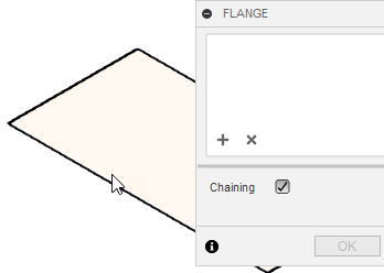
 (Design workspace > Sheet Metal tab > Create panel > Flange) to open the Flange dialog.
 - In the canvas, select the sketch profile.
- In the Flange dialog, set the Operation to
 New Component
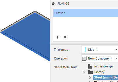
- Click OK to apply the command and close the dialog.Note: The sheet metal component is labelled in the Browser by the
 icon.
icon.
- Click
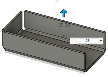
- Create the sheet metal flange from the two long edges and one short edge of the base flange. Set the height to 25 mm, and accept the default settings for the rest of the dialog options: Bend Position set to Inside, and the Angle set to 90 degrees.
- Click (Design workspace > Sheet Metal tab > Create panel > Flange) to open the Flange dialog.
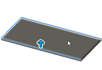
- In the canvas select the two long edges and one short edge, where the flanges will be created.Note: You may want to zoom in and confirm that you have selected the inside edge in all three cases.
- In the grip, type 25 to specify the height, or if the grip is not visible, set the Height to 25 mm in the Flange dialog.Note: Flanges created from co-planar edges automatically miter at corners that would otherwise interfere. You can change the Miter Option in this dialog.
- Click OK to apply the command and close the Flange dialog.
- Click
Part 2: Create and apply a new rule
The sheet metal component uses the default rule, which specifies certain shapes and thicknesses. In this activity you
- Create a new rule, to change the shape and thickness of the flange
- Apply the new rule to the part.
Steps
- Create a new Sheet Metal Rule using Steel mm as the Library material, and set the Thickness to 1.5 mm. Define the bend and corner relief attributes as follows:
- Change the Bend Radius to Thickness * 1.15
- Change the 2 Bend Intersection Relief shape to Square
- Change the Relief size to Thickness * 3.0.
- Click
 (Design workspace > Sheet Metal tab > Modify panel > Sheet Metal Rules) to open the Sheet Metal Rules dialog.
 - In the Sheet Metal Rules dialog, expand
 Library, select Steel (mm) (default), then click
  New Rule
 - In the New Rule dialog, type a name for the new rule, then set the Thickness to 1.5 mm.
- Expand Bend Conditions and set the Bend Radius to Thickness * 1.15
- Expand Corner Conditions and set the 2 Bend Intersection Relief shape to Square, and the Relief size to Thickness * 3.0
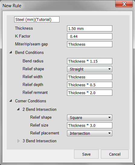
- Click Save to accept the changes and close the New Rule dialog.
- Click Close to close the Sheet Metal Rules dialog.
- Click
- Apply the new rule to your design.
- In the Browser, expand Component 1:1.Notice that there is a Rule node indicating the name of the rule used for the sheet metal part.
- Hover over Rule: Steel (mm), then click Switch Rule to open the Switch Sheet Metal Rule dialog.
- In the Switch Sheet Metal Rule dialog, expand Library and select your new rule, which is probably at the bottom of the list.
- Click OK to apply the changes and close the dialog.The new rule is changed in the browser, and the part is updated accordingly.
- In the Browser, expand
Part 3: Create a flat pattern and drawing for manufacture
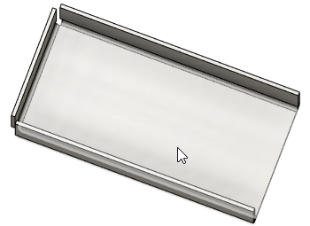
A flat pattern is the 2D shape of the sheet metal part before it is formed, and is used to create drawings for manufacturing. Flat patterns show bend lines, bend zones, center lines, and the shape of the entire part with all bends flattened and bend factors considered.
In this activity, you
- Create a flat pattern from the sheet metal part
- Switch workspace and create a drawing view using the flat pattern.

Prerequisites
- Activity 2 is completed.
Steps
- Create a flat pattern from the sheet metal part.
- Click
 (Design workspace > Sheet Metal tab > Create panel > Create Flat Pattern) to open the Sheet Metal Rules dialog.
 - In the canvas, select the stationary face of the part, from which all flanges are unfolded.
- In the Create Flat Pattern dialog, click OK to create the flat pattern and close the dialog.
- Click
 (Design workspace > Flat Pattern Solid tab > Finish Flat Pattern panel > Finish Flat Pattern) to return to the Sheet Metal tab.Notice that a Flat Pattern node is created in the Browser.
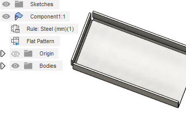
- Click
- Create a drawing view from the flat pattern.Note: You need to save the design, in order to create your drawing.
- In the Browser, hover over Flat Pattern and click the Activate Flat Pattern radio button to activate the Flat Pattern environment.
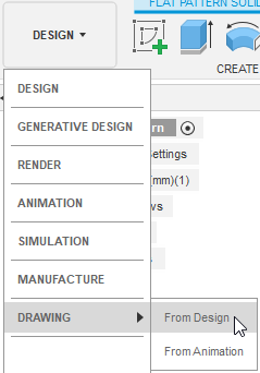
- Change Workspace from Design to Drawing from Design.Note: If you haven’t saved your design, you are prompted to do so now.
- In the Create Drawing dialog, click OK to close the dialog and activate the Drawing Workspace.
- On the new drawing document, click the location where you want to place the base view.Note: You can change the scale of the drawing, and other attributes in the Drawing View dialog.
- In the Drawing View dialog, click OK to apply the command and close the dialog.Note: To add a representation of the folded part, click
 (Drawing Workspace > Drawing Views panel > Base View) and click on the drawing to place it.
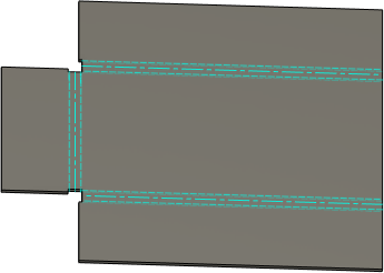
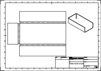 Note: The size of the flattened bend zones is determined by the Unfold Rule defined within the active Sheet Metal Rule.
- In the Browser, hover over