You can create sketch geometry in Fusion 360, in relation to the XY, YZ, and ZX origin planes, or at any plane in 3D space, to drive the shape and size of the bodies in your design. Sketches are comprised of two-dimensional geometry like lines, circles, arcs, points, and splines. Sketches are created on a plane or existing flat face of a body. You can draw sketch geometry or project edges from existing faces. You can also use dimensions, constraints, and parameters to fully define sketch geometry. This ensures you can control the form of the 3D bodies you create from your sketches.
- Sketch Contextual Tab
- Sketch Palette dialog
- Everything You Need To Know About Lines & Points
- Drawing rectangles, 2-point, 3-point & center – When to Use Each
- Draw The Circles Wide in Fusion 360 (Bonus: Ellipses)
- Three Ways to Draw Arcs
- Use Polygons Your Way
- How To Make All Kinds Of Slots
- Draw Better Curves with Splines & The Conic Curve
Sketch Contextual Tab
When you create a new sketch ![]() or edit an existing sketch, the Sketch contextual tab displays alongside the other toolbar tabs on the toolbar.
or edit an existing sketch, the Sketch contextual tab displays alongside the other toolbar tabs on the toolbar.
The Sketch contextual tab contains tools that let you create, modify, and constrain 2D and 3D sketches that drive the 3D geometry of a design.

You can still access the other visible toolbar tabs like Solid and Surface while you’re editing an active sketch, in order to use commands like Extrude. However, when you invoke a 3D modeling command while you’re editing an active sketch, the sketch is finished automatically and the Sketch tab disappears.
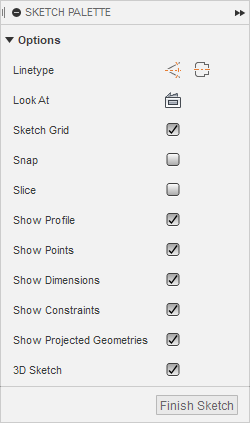
Sketch Palette dialog
When you create a new sketch ![]() or edit an existing sketch, the Sketch Palette dialog displays in the canvas.
or edit an existing sketch, the Sketch Palette dialog displays in the canvas.
You can control the following options in the Sketch Palette dialog:
- Feature Options: Displays options specific to the active sketch command.
- Linetype: Converts selected sketch geometry to a different linetype.
- Construction: Creates construction geometry.
- Centerline: Creates centerline geometry.
- Look At: Rotates the camera to look directly at the active sketch plane.
- Sketch Grid: Shows or hides the sketch grid in the canvas.
- Snap: Enables or disables the ability to snap to the sketch grid.
- Slice: Temporarily cuts through bodies where they intersect with the active sketch plane.
- Show Profile: Shows or hides blue shading for closed sketch profiles.
- Show Points: Shows or hides sketch points.
- Show Dimensions: Shows or hides sketch dimensions.
- Show Constraints: Shows or hides sketch constraints.
- Show Projected Geometries: Shows or hides projected geometry in the active sketch.
- 3D Sketch: Enables or disables the ability to sketch in 3D.
Everything You Need To Know About Lines & Points
The Line ![]() tool in the Sketch > Create panel lets you create a connected series of lines and arcs as sketch geometry or construction geometry in an active sketch in Fusion 360.
tool in the Sketch > Create panel lets you create a connected series of lines and arcs as sketch geometry or construction geometry in an active sketch in Fusion 360.
Drawing rectangles, 2-point, 3-point & center – When to Use Each
The rectangle tools in the Sketch > Create panel let you create different types of rectangles as sketch geometry or construction geometry in an active sketch in Fusion 360.
- 2-Point Rectangle
 The 2 points are opposite corners of the rectangle. You click to place the first corner point, then click to place the second corner point. Alternatively, you can specify the width and height values.
 - 3-Point Rectangle
 The 3 points define the width, direction, and height of the rectangle. You click to place the first corner point, then click to place the second point. Alternatively, you can specify the first distance value, then click to place the point. Then you click to place the third point or specify the second distance value.
 - Center Rectangle
 Creates a rectangle defined by the center point and one corner point. You click to place the first point as the center of the rectangle, then click to place a corner point or specify width and height values.
Draw The Circles Wide in Fusion 360 (Bonus: Ellipses)
The circle tools in the Sketch > Create panel let you create different types of circles as sketch geometry or construction geometry in an active sketch in Fusion 360.
- Center Diameter Circle
 You click to place the center point, then specify the diameter.
 - 2-Point Circle
 You click to place 2 points that define the diameter of the circle.
 - 3-Point Circle
 You click to place 3 points that lie along the circumference of the circle. The points define the size and position of the circle.
 - 2-Tangent Circle
 You select 2 lines, then specify the radius of the circle.
 - 3-Tangent Circle
 You select 3 lines that the circle will be tangent to.
 - Ellipse
 First place to major axis, then the minor axis of the ellipses. These perpendicular lines will form the inside of the resulting ellipses.
Three Ways to Draw Arcs
The arc tools in the Sketch > Create panel let you create different types of arcs as sketch geometry or construction geometry in an active sketch in Fusion 360.
- 3-Point Arc
 You click to place the start point, place the end point, then place a third point that lies along the arc.
 - Center Point Arc
 You click to place the center point, place the start point, then place the end point. Alternatively, you can specify an angle value.
 - Tangent Arc
 You click to place the 2 end points. The arc will maintain tangency with the geometry it connects to at each end.
Use Polygons Your Way
The polygon tools in the Sketch > Create panel let you create different types of polygons as sketch geometry or construction geometry in an active sketch in Fusion 360.
- Circumscribed Polygon
 You click to place the center point of the polygon, specify the number of sides, then click to place the midpoint of an edge. Alternatively, you can specify a distance, then click to place a point.
 - Inscribed Polygon
 You click to place the center point of the polygon, specify the number of sides, then click to place a vertex point. Alternatively, you can specify a distance, then click to place a point.
 - Edge Polygon
 You click to place the start point and end point of one edge. Alternatively, you can place the start point, then specify the distance and angle. You specify the number of sides, then click to place a point to define the orientation of the polygon.
How To Make All Kinds Of Slots
The slot tools in the Sketch > Create panel let you create different types of slots as sketch geometry or construction geometry in an active sketch in Fusion 360.
- Center to Center Slot
 You click to place the center of each slot arcs, then click to define the slot width or specify the diameter of the slot arcs.
 - Overall Slot
 You click to place the start point and end point of the slot centerline, then click to define the slot width or specify the diameter of the slot arcs.
 - Center Point Slot
 You click to place the slot center, place the center of the slot arc, then click to define the slot width or specify the diameter of the slot arcs.
 - 3 Point Arc Slot
 You click to place the start point and end point of the slot center arc, place the third point of the center arc or specify the center arc radius, then click to define the slot width or specify the diameter or radius of the slot arcs.
 - Center Point Arc Slot
 You click to place the center point of the slot, place the start point and end point of the slot center arc, then click to define the slot width or specify the diameter or radius of the slot arc.
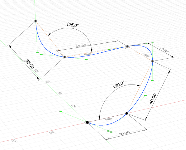
Draw Better Curves with Splines & The Conic Curve
The spline tools in the Sketch > Create panel let you create different types of splines as sketch geometry or construction geometry in an active sketch in Fusion 360. A spline is a smooth, freeform curve that passes through or near a set of points that influence the shape of the curve. There are two kinds of splines in Fusion 360. You can create open or closed splines.
Fit Point Spline ![]() Click to place the first point, place additional fit points, then click the Check icon to complete the spline.
Click to place the first point, place additional fit points, then click the Check icon to complete the spline.
Control Point Spline ![]() creates a smooth curve driven by a control frame that you create by placing a series of points. Control Point Splines are also known as CV Splines. Click to place the first point, place additional control points, then click the Check icon to complete the spline.
creates a smooth curve driven by a control frame that you create by placing a series of points. Control Point Splines are also known as CV Splines. Click to place the first point, place additional control points, then click the Check icon to complete the spline.
- A control point spline does not usually pass through the control points, except for the first and last points. In contrast to fit points, control points define the underlying frame used to calculate the curve.
- Control points apply tension to the spline in a given direction. If you pull a control point farther away, the tension on the curve increases in that area. If you push a control point closer, the tension relaxes.
- In most cases, you need more control points than fit points to define a given shape, because each control point has less influence on the overall curve than a fit point does.
- Control point splines do not offer tangent/curvature handles. To apply more refined shape control, add more points.
- Conic Curve
 creates a curve driven by endpoints and Rho value. The endpoints define the position of the curve. The Rho value defines the shape. Depending on the Rho value, the curve can be elliptical, parabolic, or hyperbolic. You click to place the start point, end point, then the top of the vertex. Use the guidelines to create a tangency constraint, then specify the Rho value to create the desired shape.