
Routing is the high speed mechanical cutting of woods, plastics, metals, and other resilient materials, using a spinning cutting tool often called a router bit or end mill. Routers can be handheld, table-mounted, or computer-controlled. Any tool with a spinning bit designing to cut perpendicular to the material (laterally) can be considered a routing operation. Routing is a common cutting task for many woodworking projects (creating grooves, carving patterns) or metal applications (flattening, shaping, producing parts).
Milling and Routing are fundamentally the same type of cutting, and part of a broad group of Rotary Tools. In milling, the workpiece often moves along the x/y plane with the cutting tool moving along the z axis. In routing, the workpieces is often stationary, moving the router in the x, y, and z, axis. This distinction is discussed in detail in the context of CNC machines here.
Drilling vs Milling
Milling & routing are primarily lateral-type cuts. Drilling is specifically for penetrating a material along a single axis. Drill bits are optimized to penetrate and remove material from a hole. End mills having cutting blades or flutes on their sides to perform lateral cutting, and are often not effectively designed for plunging. Computer-controlled cutting can overcome this by plunging with a spiral motion into the material.
Types of Router Cuts
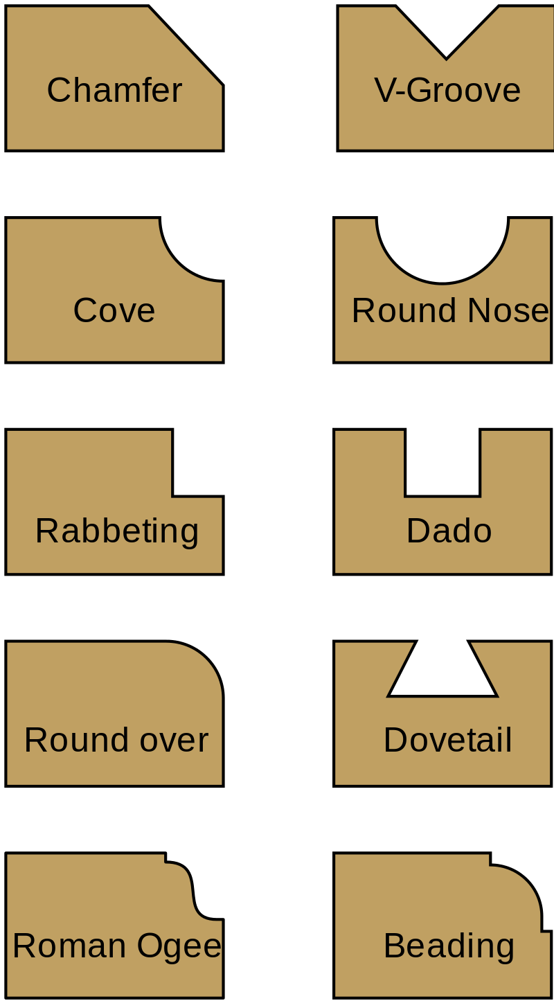
Rotating cutting bits, depending on their shape, can accomplish a variety of cutting tasks. Chamfer, cove, rabbeting, round over, beading, and specialty shapes (e.g. Roman Ogee) are useful in creating decorative profiles and finishing the edges of pieces.
V-groove, round nose, dado, rabbeting, and dovetail are useful in creating various types of assembly.
The V-Groove bit is commonly used in sign-making and letter/design carving.
V-Grooves
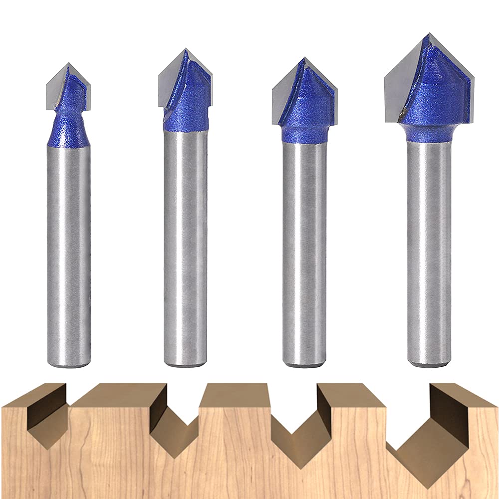
V-Groove bits are extremely useful in carving detailed designs with CNC work. The pointed tip and tapered cutting edges allow for varying widths of cuts by varying the depth. By taking the taper angle, commonly 60 or 90 degrees, you can determine the width of the cut by the depth of the bit. This allows for making very small, precise cuts and larger coarser cuts with the same bit.
Surfacing Bits
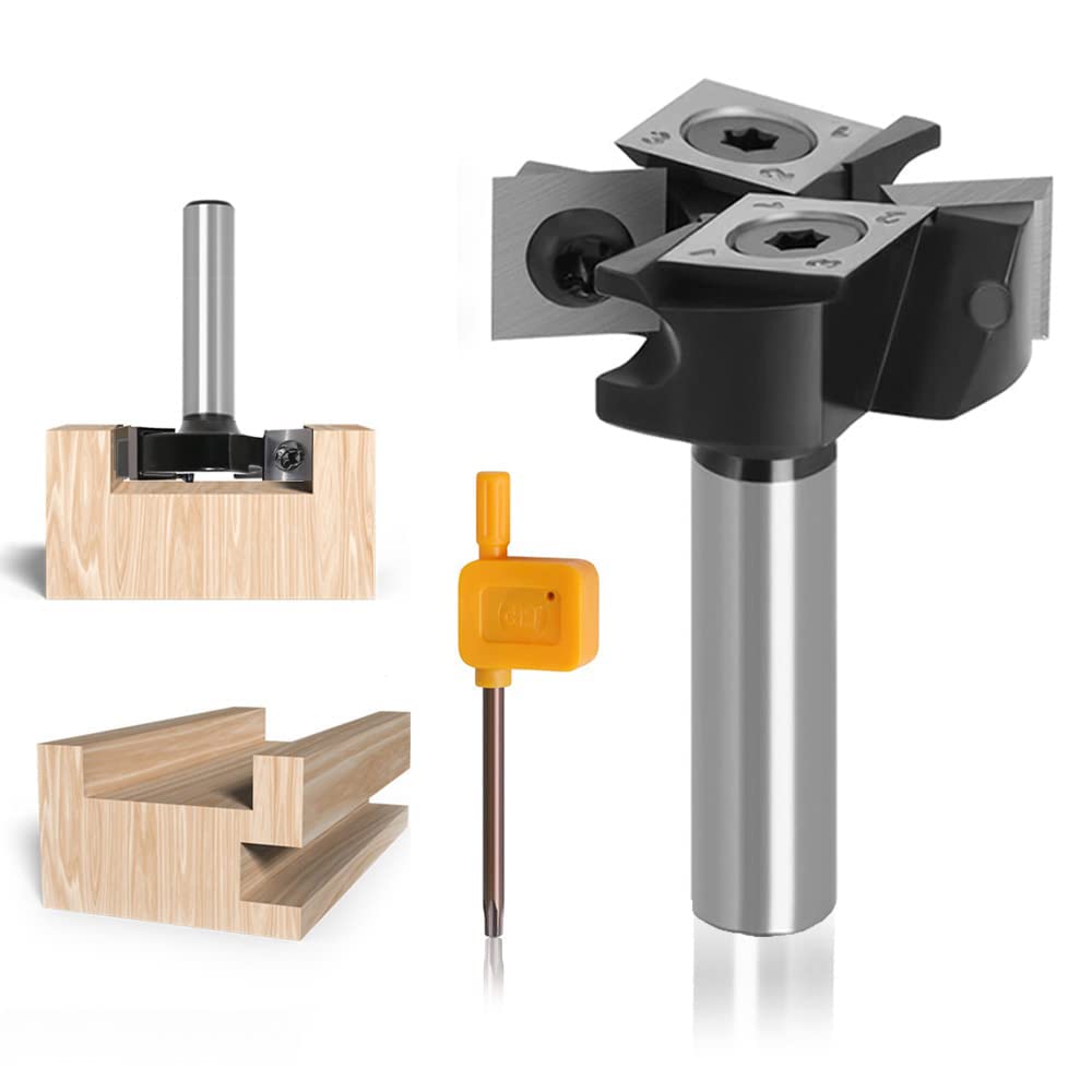
Surfacing bits are designed to create flat, plane surfaces. Their cutting depth is very limited (~2mm). They are a type of finishing operation. They are specifically useful where other flattening (plane) operations can’t occur, such as flattening end-grain wood.
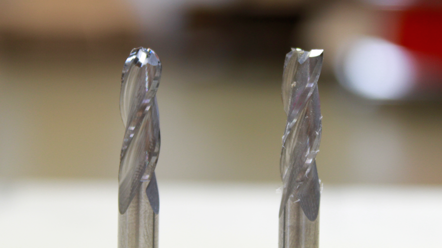
Standard woodworking bits
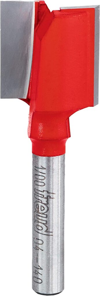
This is a standard router bit for woodworking. The two rotating blades cut laterally to remove the bulk of the material.
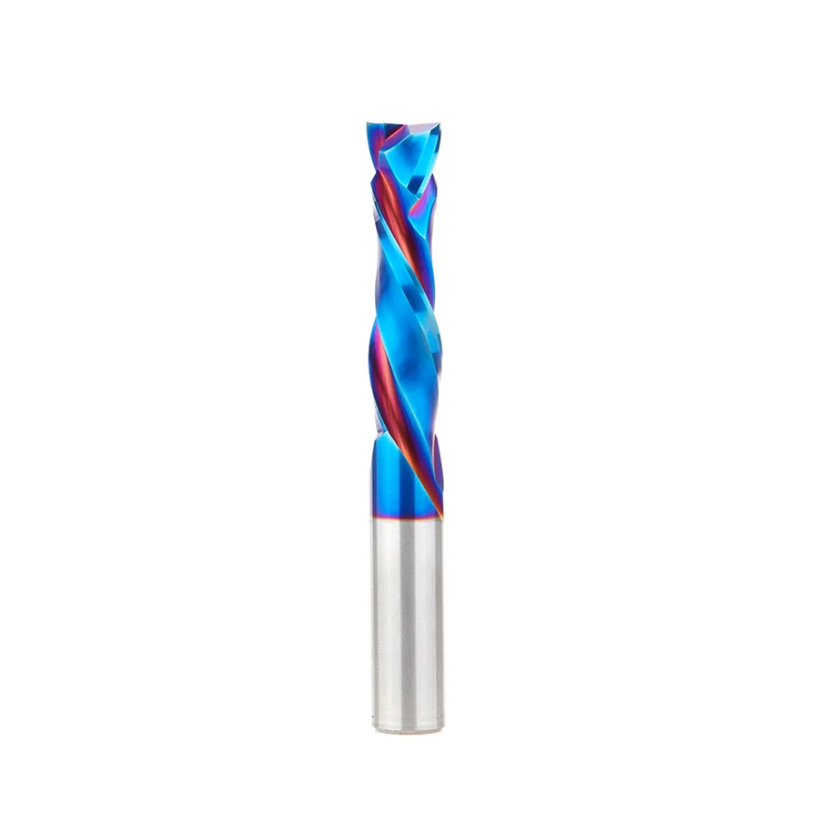
Spiral routing bits have cutting flutes instead of straight blades. Flutes range from 1 (“open”) to as many as 6.
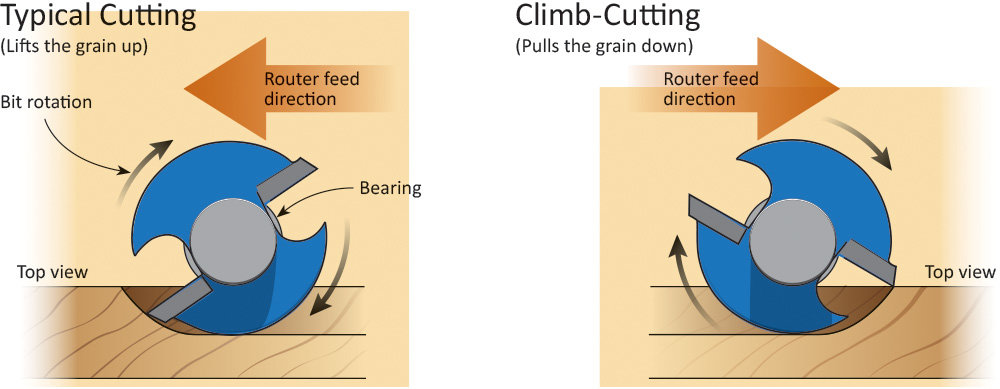
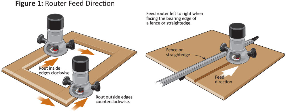
Feed Direction
COnventional milling (typical) is the safest and recommended direction for cutting at a router table and trim router. This prevents backlash from the workpiece and takes controlled cuts from the workpiece. It is possible ti achieve a quality finish with climb cutting, this is a more challenging cut for the end mill and therefore requires stabilization, as in that of a CNC setup.
Anatomy of an Endmill
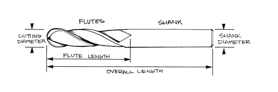
Shank: The diameter of the non-cutting end of the cutter. The shank diameter determines what size collet should be used to hold the cutter in the spindle.
Overall Length (OAL): The total length of the cutter. This can be determined by measuring from one end of the cutter to the other. Tip to Tip.
Length of Cut (LOC): The total length of the cutting surface of the cutter. If this dimension is less than the dimension of the shank, the LOC is effectively how far down the cutter can plunge (total) into the material.
Flutes: The number of cutting surfaces found on the cutter. For example, a 2 flute cutter has two cutting edges, a 3 flute cutter has 3 cutting edges.
Cutting Diameter: The diameter of the cutting area of the end mill. Note, this can be different from the shank size of the cutter. This is also called ‘Cutting Edge Diameter’
Choosing the Right Tool
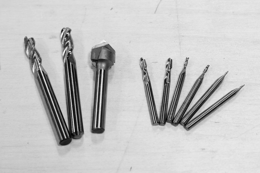
End Mills
Endmills generally come in 2 varieties: Square End Mills and Ballnose end mills.
Aside from the shape of the endmill, the tip geometry also varies between types, determining the way the chips are ejected and effecting the smoothness of the finish.
Up-Cut
Up-cut end mills ‘pull’ the chips UP and out of the slot. These tend to leave a smooth finish on the bottom of the material.
Down-Cut
Down-Cut end mills ‘push’ the chips down into the slot. These tend to leave a smooth finish on the top of the material.
Compression
Compression cut endmills have a mixture of up-cut and down-cut flutes, creating a smooth finish on the top and bottom of the material.
Note: The cutters we stock in the store are all of the up-cut variety. If you’re interested in another variation, please let us know by sending an email to sales@carbide3d.com
Scallops:
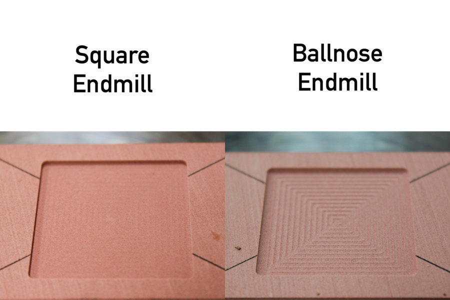
Square end mills will cut a smooth flat bottom surface, while Ballnose End mills will not cut a flat bottom surface, instead they will leave scallops.
Contours
Ball nose end mills are known to be used for contoured or organic shapes. They do a nice job of getting in the nooks and crannies of contours without disturbing the surrounding material.
Square End mills are commonly used for 2D and 2.5D parts, where flat bottoms and vertical walls define the design.