This tutorial leads you through the process of creating components from bodies in order to create an assembly that enables motion.
In this tutorial, you perform the following actions:
- Create components from bodies and organizing components within subassemblies.
- Create a series of As-built Joints to enable motion within the assembly.
- Fix the motion of an assembly, and build out an assembly by copying and pasting components.
Tip: If you are having trouble finding a specific command, you can search for commands by name by hitting the “S” key on your keyboard. This displays the toolbox where you can search for specific commands. Read more about the toolbox here.
Activity 1: Get the dataset and create the subassembly
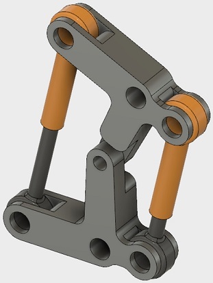
In this activity, you open the piston assembly model, convert the bodies to components, and create the Piston subassembly.
Prerequisites
- Fusion 360 is started.
- Data file location: Samples > Basic Training > 06 – Assemblies > Piston Linkage.
- Open the Piston Linkage model.
- If necessary, click Show Data Panel
 . The Data Panel appears at the left side of the program window.
 - In the Data Panel, under Samples, open Basic Training > 06 – Assemblies > Piston Linkage.
- If necessary, click Show Data Panel
- Because the design is read-only, save a copy to a personal project.
- From the top left corner, click File > Save As.
- In the Name box, make sure the name is My Piston Linkage.
- To the right of the Location box, click the Down Arrow icon.
- Either select an existing folder or create a new folder by clicking New Project, typing My Model Tutorials, and pressing keyboard Enter.
- To save the project file in the Project list, click the name of the desired folder or click the My Model Tutorials folder.
- Click Save.
- Convert the bodies to components.
- To convert all four bodies to components, right click on the Bodies folder in the browser, and click Create Components from Bodies.
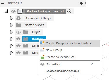
- The components should appear in separate folders in the browser.
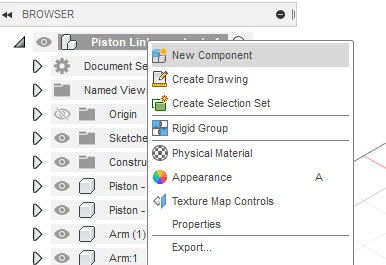
- Create the piston subassembly.
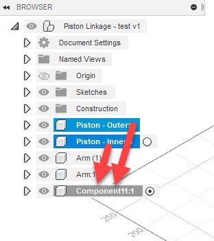
- To create a blank component in the main assembly, right click on the main assembly branch, and click New Component.
- Drag the two Piston components into the new subassembly:
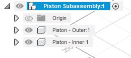
- To rename the new subassembly, double click on its folder, and enter Piston Subassembly. Note that the component icon switched to an assembly icon.
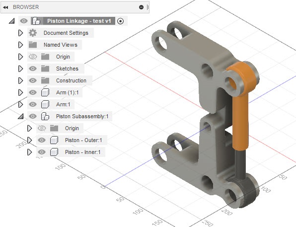
- To reactivate the main assembly, right click on the top node (Piston Linkage), and click Activate.
Activity 1 summary
In this activity, you opened the Piston assembly model, converted the bodies to components, and created the Piston subassembly.
Activity 2: Create As-built joints
In this activity, you create a series of Revolute and Cylindrical As-built joints within the assembly.

- Add a Revolute As-built joint between the two arms. This step allows the two arms to rotate about their shared pivot point.
- From the Design workspace, on the Solid tab, click Assemble > As-built Joint.
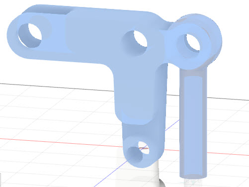
- Select the two Arm parts:
- To set the joint type, on the As-built joint dialog, set the Type to Revolute.
- To define the position, select the circular edge where both arms contact each other:
- To complete the action, on the As-built joint dialog, click OK.
- Add a Cylindrical As-built joint between the inner and outer piston components. This step allows the inner piston component to slide within the outer component.
- From the Design workspace, on the Solid tab, click Assemble > As-built Joint.
- Select the two piston components:
- To set the joint type, on the As-built joint dialog, set the Type to Cylindrical.
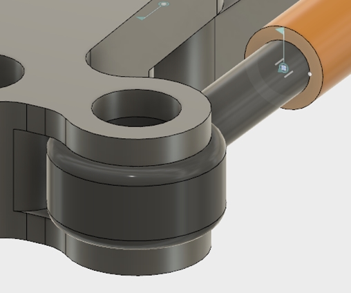
- To define the position, select the center point on the face at the end of the Piston – Outer component, which is where the other Piston slides into it.To select the center point, hover over the circular edge of the end-surface, hold the Ctrl key (Cmd on Mac), and click on the center point. The Ctrl key (Cmd key on Mac) locks the selection to the specific face, which makes selecting the related center point much easier:
- To complete the action, click OK.
- Add a Revolute As-built joint between the Piston Subassembly and the Arm at the bottom.This step allows the arm and the piston subassembly to rotate relative to each other about a common point at the bottom of the piston subassembly.
- To reactivate the main assembly, right click on the top node (Piston Linkage), and click Activate.
- From the Design workspace, on the Solid tab, click Assemble > As-built Joint.
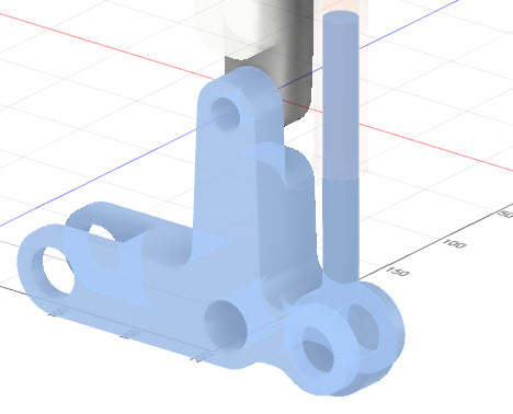
- Select the bottom Arm component and the Piston – Inner component:
- To set the joint type, on the As-built joint dialog, set the Type to Revolute.
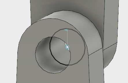
- To define the position, select the center point of the inner cylindrical face on the Piston – Inner component.To select the center point, hover over the inside cylindrical surface of the Piston – Inner component, hold the Ctrl key (Cmd on Mac), and click on the center point:
- To complete the action, click OK.
- Add a Revolute As-built joint between the Piston Subassembly and the Arm at the top.This step allows the arm and the piston subassembly to rotate relative to each other about a common point at the top of the piston subassembly.
- From the Design workspace, on the Solid tab, click Assemble > As-built Joint.
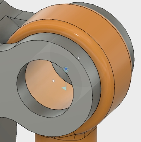
- Select the top Arm component and the Piston – Outer component:
- To set the joint type, on the As-built joint dialog, set the Type to Revolute.
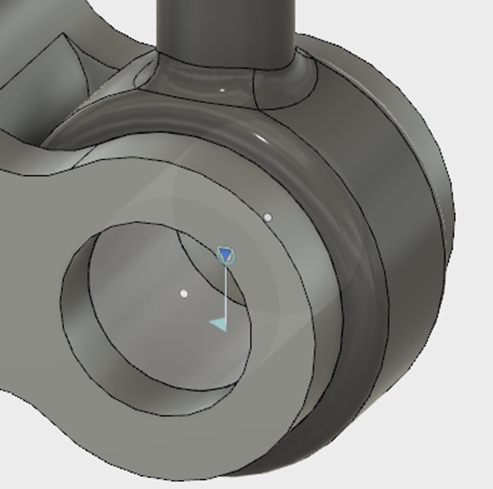
- To define the position, select the center point of the inner cylindrical face on the Piston – Outer component.To select the center point, hover over the inside cylindrical surface of the Piston – Outer component, hold the Ctrl key (Cmd on Mac), and click on the center point:
- To complete the action, click OK.
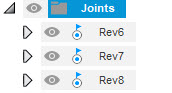
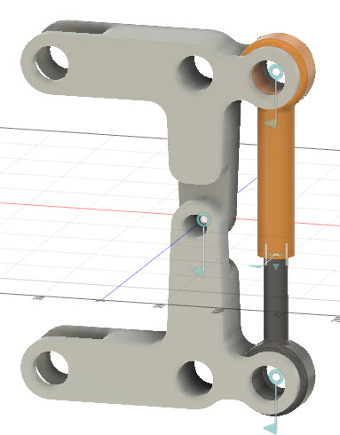
- To view the joints, right click on the Joints folder in the Browser, and toggle Show/Hide. The visibility glyph should be active:
Activity 2 summary
In this activity, you created several As-built joints to control the motion of parts in the assembly relative to each other. You created a Revolute joint between the two arms, a Cylindrical joint between the piston components, and Revolute joints between the upper and lower piston components and the corresponding arms of the assembly.
Activity 3: Ground the component and add subassembly
In this activity, you fix the motion of the assembly by grounding the lower Arm component. Additionally, you build out the assembly by adding another instance of the Piston subassembly and creating As-built joints to define the relative motion.
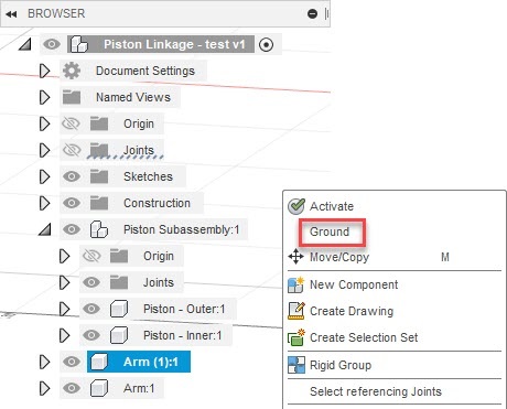
- Fix the model in space by grounding the lower Arm component.
- To ground the lower arm, from the Browser, right click on Arm(1), and click Ground.
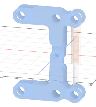
- To test the motion of the assembly, click on the top Arm component and drag.
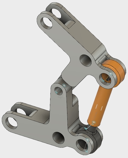
- To reset the position of the assembly, on the Position tab, click Revert.
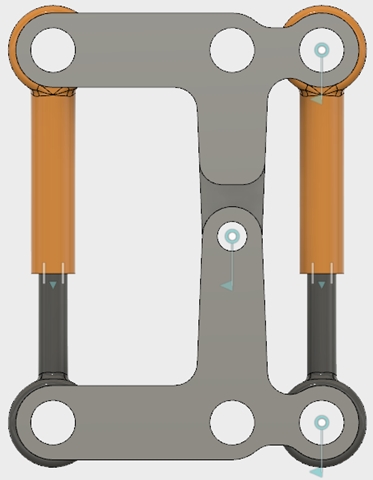
- Copy the Piston subassembly and position it so that they line up with the mounting holes on the other side of the two arms.
- To copy the Piston subassembly, from the Browser, right click on Piston Subassembly, and click Copy.
- To paste the copy of the Piston subassembly, press keyboard Ctrl V (or Cmd V on the Mac).
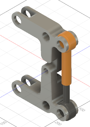
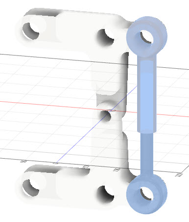
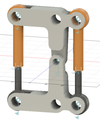
- To position the new subassembly, drag it to the left 180 mm so that the piston mounting holes line up with the two arms:
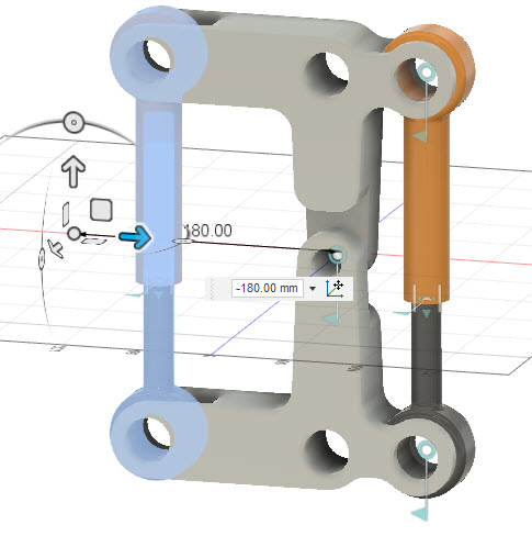
- To finish the command, press keyboard Enter.
- Add a Revolute As-built joint between the Piston subassembly and the Arm at the bottom.
- From the Design workspace, on the Solid tab, click Assemble > As-built Joint.
- Select the bottom Arm component and the Piston – Inner component on the new Piston Subassembly.
- To set the joint type, on the As-built joint dialog, set the Type to Revolute.
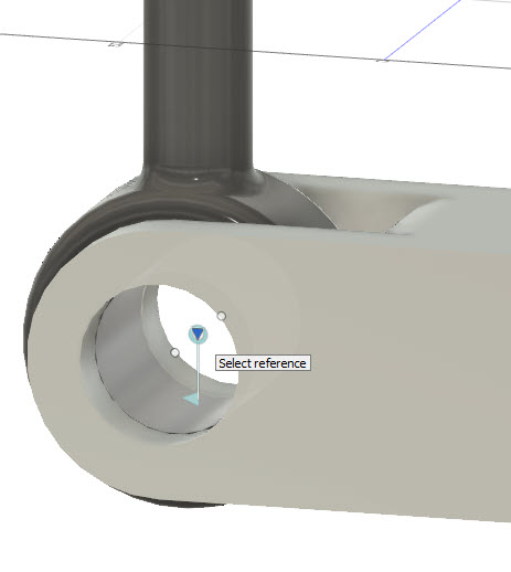
- To define the position, select the center point of the inner cylindrical face on the Piston – Inner component.To select the center point, hover over the inside cylindrical surface of the Piston – Inner component, hold the keyboard Ctrl key (Cmd on Mac), and click on the center point:
- To complete the action, on the As-built joint dialog, click OK.
- Add a Revolute As-built joint between the Piston subassembly and the Arm at the top.
- From the Design workspace, on the Solid tab, click Assemble > As-built Joint.
- Select the top Arm component and the Piston – Outer component on the new Piston Subassembly.
- To set the joint type, on the As-built joint dialog, set the Type to Revolute.
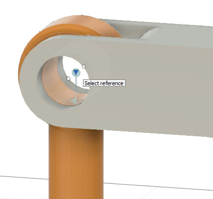
- To define the position, select the center point of the inner cylindrical face on the Piston – Outer component.
- To complete the action, on the As-built joint dialog, click OK.
Note: you do not need to create a Cylindrical As-built joint between the components of the second piston subassembly because the joint in the original subassembly was copied with the subassembly.
Activity 3 summary
In this activity, you fixed the motion of the assembly by grounding the lower Arm part. You then copied the Piston subassembly and aligned the copy to the other set of mounting holes in the Arm parts. Finally, you defined the relative motion of the new subassembly by assigning Revolute As-built joints.
