When working with a bottom-up strategy, the components in an assembly are made independent of one another before being inserted into the same design. When in the same design, you can position the components correctly and manually add joints to define how components move relative to each other.
In this tutorial, you add joints to components of a clamp assembly to control how the clamp moves.
Prerequisites
- Click
 Data Panel > New Project and enter the project Manual Joints to create a project folder. You will assemble the clamp in this project.
 - Click Data Panel > Basic Training > 06 – Assemblies. Double-click to open the following parts:
- Base
- Clamp
- Connector
- Grip
- Lever
- Shaft
- Click File > Save as and save each of the parts, in the Manual Joints project.
- Close each of the parts, once saved to the new location.
- Double-click the Manual Joints project to open it and ensure the files are in the project.
- Ensure a new untitled design is open.
- Click Save to save the design with the name Clamp Joints in the Manual Joints location.
Activity: Assemble the clamp and add joints
In this activity, you insert parts into the Clamp Joints design and add joints to represent the actions of the parts and overall design.
- Insert the Base into the Clamp Joints design and Ground it at the location where it has bee inserted.
- Right-click the Base design in the Data Panel and select Insert into Current Design.
- Click OK on the Move/Copy dialog that opens as the base is placed in the design to accept its default location.
- Right-click on the Base node in the Browser and select Ground, to fix the Base in its current location.

- Insert the Lever and use a Revolute joint to attach it to the base.
- Right-click the Lever design in the data panel and select Insert into Current Design.
- Use the Z-translation manipulator of the Move/Copy dialog to move the Lever off the base and click OK.

- Click Solid > Assemble > Joint.
- Set the Motion type to Revolute on the Joint dialog. This joint allows only one rotational degree of freedom.
- Click the center of the pin on the lever for the first component selection. The snap location is a triangle glyph and is difficult to see because it is inside the pin.

- Click the center of the pin hole on the base for the second component selection. The snap location is a triangle glyph. Hover over the inside wall of the hole to highlight it. Press the Ctrl key and then select the center snap location.

- Click Flip on the Joint dialog to properly orient the parts.
- Click OK to finish the joint.

- Create a joint origin midway between the open holes on the Lever.
- In the Browser, right-click on the Lever design and select Open.

- Click Solid > Assemble > Joint Origin.
- Set the Type to Between two faces.
- Select the inside faces of the lever arms as the two faces.

- Select the edge of one of the holes to define the joint origin in the center of the hole between the planes.
- Click OK to finish the Joint Origin.
- Save the Lever design.
- Prepare to add the Connector to the Camp Joints design.
- Go back to the Clamp Joints design.In the Clamp Joints design, the Lever is out of date, indicated by a yellow triangle icon on the Lever node, in the browser, because you added a joint origin.
- Right-click on the Lever node, in the browser and select Get Updates. Note: the Context menu may say Get Latest.
- Click on the lever and move it to its forward position. The exact location is not critical.

- Insert the Connector and use a Revolute joint to attach it to the lever using the joint origin created.
- Right-click the Connector design in the data panel and select Insert into Current Design.
- Use the Y-translation manipulator of the Move/Copy dialog to move the Lever off the base and click OK.

- Click Solid > Assemble > Joint and set the Motion type to Revolute on the Joint dialog.
- Click Capture Position on the dialog to indicte you want to use the current position of the connector.
- Click the center of the pin on the Connector for the first component selection.

- Click the joint origin you created for the second component selection and click OK.

- Ensure the connector is properly assembled to the lever.

- Insert the Shaft and use a Cylindrical joint to attach it to the base. The cylindrical joint allows the part to rotate and translate around one axis.
- Right-click the Shaft design in the data panel and select Insert into Current Design and click OK to accept the insert location.
- Click Solid > Assemble > Joint and set the Motion type to Cylindrical on the Joint dialog.
- Hover over the end of the shaft and select the center for the first component selection.

- Select the shaft hole on the end of the base for the second component selection and click OK.

- Ensure the shaft is properly assembled to the base.

- Join the Shaft to the Connector with a Revolute joint.
- Click Solid > Assemble > Joint and set the Motion type to Revolute on the Joint dialog.
- If you get a dialog indicating components have moved, click Capture Position.
- Click in the triangular center glyph, of the hole, in the Shaft for the first component selection.

- Press the Ctrl key and then select the triangular center glyph, of the pin, on the Connector for the second component selection and click OK.

- Ensure the shaft is properly assembled to the connector.

- Insert the Clamp and use a Ball joint to attach it to the base. The ball joint allows the part to rotate around three axes.
- Right-click the Clamp design in the data panel and select Insert into Current Design.
- Click Solid > Assemble > Joint and set the Motion type to Ball on the Joint dialog.
- If you get a dialog indicating components have moved, click Capture Position.
- Select the center of the ball socket on the clamp for the first component selection.

- Select the center of the shaft ball for the second component selection and click OK.

- Ensure the clamp is properly assembled to the shaft.

- Join the Grip to the Lever with a Rigid joint.
- Right-click the Grip design in the data panel and select Insert into Current Design and click OK to accept the insert location.
- Click Solid > Assemble > Joint and set the Motion type to Rigid on the Joint dialog.
- If you get a dialog indicating components have moved, click Capture Position.
- Click on the inside grip face, but not on any snap points. This limits the selection of snap points to only the ones on this face.

- Click on the snap point that represents the center of the radius on the top of the grip.

- Click on the center of the lever handle radius the corresponds to the grip location you selected and click OK.

- Ensure the grip is properly assembled to the lever.

Tutorial conclusion: Manually adding joints
In this tutorial, you applied joints to components of a clamp assembly to control how the clamp moves. The joint types you applied included:
- Resolute
- Cylindrical
- Ball
- Rigid
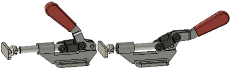
Clamp with all components assembled and with joints representing how the part moves