In the Design workspace in Fusion 360, you can create joints between components in an assembly.
A Joint is a mechanical relationship that defines the relative position and motion between 2 components in an assembly.
As you design an assembly with moving components, simulating motion is an important part of the prototyping process. In Fusion 360, joints reduce the complexity of component relationships by helping you focus on what components can do, instead of what they can’t. This differs from other approaches like constraints or mates, which lock down available degrees of freedom (DOF) to limit motion. This requires you to understand the basic physics and math involved to ensure the components in an assembly move the way you intend.
In contrast, joints define motion between components, and only leave the required degrees of freedom open to create that motion. This reduces the need to understand the physics, and creates an understanding between the motion and the result.
Joint access points
There are 3 access points where you can interact with joints you create in an assembly:
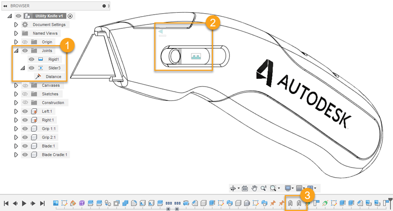
- In the Browser, within the Joints folder
- In the Canvas, directly on components, designated by the Joint type icons
- In the Timeline
Note: In the Browser, each component has its own Joints folder.
You can use the following commands in the Assemble panel to create and modify joints:
- Joint
 : Creates a joint between components that are not yet positioned in relation to each another.
 - As-Built Joint
 : Creates a joint between components that are already positioned in relation to each another.
 - Joint Origin
 : Creates and positions a joint origin on a component.
 - Rigid Group
 : Locks components together so that they move together in an assembly.
 - Tangent Relationship
 : Creates a tangent relationship between a face on a body in one component and a set of connected faces on a body in another component within an assembly.
 - Drive Joints
 : Modifies joint motion inputs, like rotation angle and distance, to control degrees of freedom.
 - Motion Link
 : Links the motion of 2 joints together.
You can right-click any existing joint, in the canvas or browser, and use the following additional commands to modify it:
- Edit Joint: Opens the Edit Joint dialog and lets you edit all settings associated with hthe joint.
- Edit Joint Limits: Opens the Edit Joint Limits dialog and lets you edit the minimum, maximum, and rest limits of the joint.
- Lock: Locks the current position and settings of the joint.
- Suppress: Temporarily removes the joint to prevent it from acting upon the components.
- Animate Joint: Animates the single joint.
- Animate Model: Animates all joints in the assembly.
Joint Types
There are 7 different types of joints in Fusion 360. You can create joints with both the Joint and As-Built Joint commands. Each joint type uses different degrees of freedom to define motion.
| Type | Description | Motion Allowed | |
|---|---|---|---|
| Rigid | Locks components together. Removes all degrees of freedom. | None | |
| Revolute | Component rotates around Joint Origin. | 1 rotation | |
| Slider | Component moves along a single axis. | 1 translation | |
| Cylindrical | Component rotates around and moves along a single axis. | 1 translation 1 rotation | |
| Pin-slot | Component rotates around one axis and moves along a different axis. | 1 translation 1 rotation | |
| Planar | Component moves along two axes and rotates around a single axis. | 2 translation 1 rotation | |
| Ball | Component rotates around all 3 axes using a gimbal system (3 nested rotations). | 3 rotation |
Note: When you create a joint, you also create a parameter that you can alter in Parametric Modeling.
Note: When you create a joint, maintaining the fewest degrees of freedom will help you test your assembly faster.