The spline tools in the Sketch > Create panel let you create different types of splines as sketch geometry or construction geometry in an active sketch in Fusion 360. A spline is a smooth, freeform curve that passes through or near a set of points that influence the shape of the curve. There are two kinds of splines in Fusion 360. You can create open or closed splines.

Fit Point Spline ![]() Click to place the first point, place additional fit points, then click the Check icon to complete the spline.
Click to place the first point, place additional fit points, then click the Check icon to complete the spline.

Control Point Spline ![]() creates a smooth curve driven by a control frame that you create by placing a series of points. Control Point Splines are also known as CV Splines. Click to place the first point, place additional control points, then click the Check icon to complete the spline.
creates a smooth curve driven by a control frame that you create by placing a series of points. Control Point Splines are also known as CV Splines. Click to place the first point, place additional control points, then click the Check icon to complete the spline.
- A control point spline does not usually pass through the control points, except for the first and last points. In contrast to fit points, control points define the underlying frame used to calculate the curve.
- Control points apply tension to the spline in a given direction. If you pull a control point farther away, the tension on the curve increases in that area. If you push a control point closer, the tension relaxes.
- In most cases, you need more control points than fit points to define a given shape, because each control point has less influence on the overall curve than a fit point does.
- Control point splines do not offer tangent/curvature handles. To apply more refined shape control, add more points.

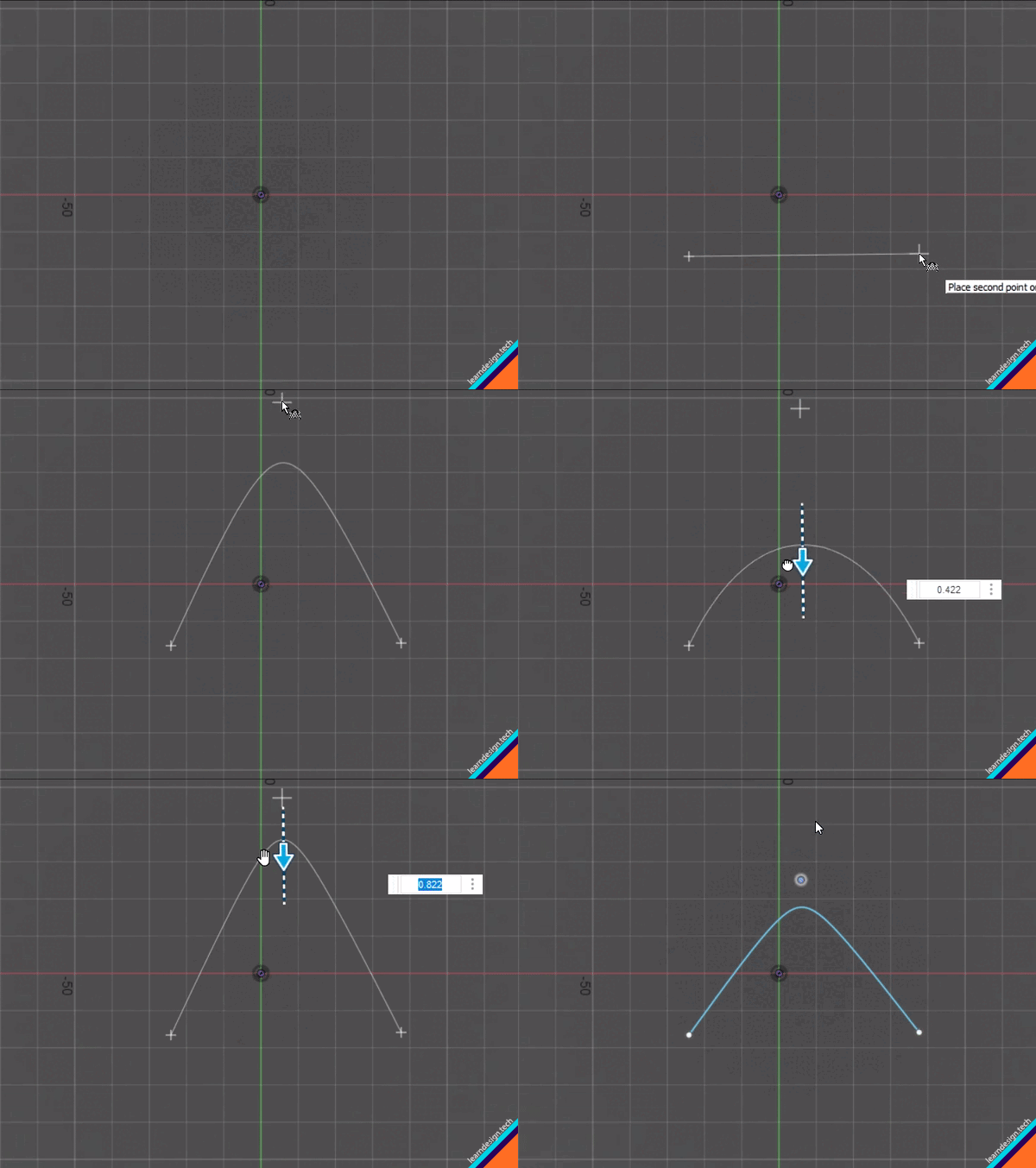
Conic Curve ![]() creates a curve driven by endpoints and Rho value. The endpoints define the position of the curve. The Rho value defines the shape. Depending on the Rho value, the curve can be elliptical, parabolic, or hyperbolic. You click to place the start point, end point, then the top of the vertex. Use the guidelines to create a tangency constraint, then specify the Rho value to create the desired shape.
creates a curve driven by endpoints and Rho value. The endpoints define the position of the curve. The Rho value defines the shape. Depending on the Rho value, the curve can be elliptical, parabolic, or hyperbolic. You click to place the start point, end point, then the top of the vertex. Use the guidelines to create a tangency constraint, then specify the Rho value to create the desired shape.
